There are six Units in Module 4.
Unit 1 focuses on Introduction to Pipe Installation and Safety, Unit 2; Piping
Services, Unit 3; Electricity on Site, Unit 4; Bracket Fabrication, Unit 5; Ancillary
Piping Equipment and Unit 6; Piping system assembly.
In this unit you will be introduced
to good practice guidelines for installing ancillary piping equipment such as
pumps, heat exchangers and valves and how best to orientate and bracket piping
coming to and from this equipment.

Learning Outcome
By the end of this unit each
apprentice will be able to:
·
Identify and describe the main ancillary piping
system components
·
Identify and select the correct pump for the
three most common pumping applications.
·
Explain why pipe lines are installed at low
level, close to walls and accessible to read instruments wherever possible.
·
Explain why safe access to equipment (e.g. heat
exchangers and pumps) is important during commissioning, maintenance and
servicing.
·
List reasons why valves are used in piping
systems.
·
Outline the importance of bracketing pipe work
around equipment to facilitate safe removal of equipment for maintenance and to
ensure that piping does not strain the equipment.
·
Describe the standard procedure for safe
start-up and commissioning of ancillary piping equipment.
·
Recognise the importance of and the need to
retain and file equipment manuals and material certification.
1.0 Ancillary Piping Components

Ancillary piping components are the additional items installed in a
piping system such as pumps, heat exchangers, valves and instrumentation. Their requirements vary depending on the media
being transported in the piping system.
Module 3 unit 2 has dealt with pumps, valves and basic instrumentation
so this module will examine the different type of common heat exchangers and
evaluate different pumps against specific pump selection criteria.
1.2Types of Heat Exchangers
A heat exchanger is a device built for
efficient heat transfer from one medium to another. The heating or cooling media
is separated from the product to be heated or cooled by a solid wall, so that
they never mix. There are three primary
classifications of heat exchangers according to their flow arrangement. In
parallel-flow heat exchangers, the two fluids enter the exchanger at the same
end, and travel in parallel to one another to the other side. In counter-flow
heat exchangers the fluids enter the exchanger from opposite ends. In a
cross-flow heat exchanger, the fluids travel roughly perpendicular to one
another through the exchanger. The
counter current design is most efficient, in that it can transfer the most heat
from the heat (transfer) medium. For
efficiency, heat exchangers are designed to maximize the surface area of the
wall between the two fluids, while minimizing resistance to fluid flow through
the exchanger. The exchanger's performance can also be affected by the addition
of fins or corrugations in one or both directions, which increase surface area
and may channel fluid flow or induce turbulence. We will deal the 2 most common types of heat
exchangers:
·
Shell and Tube Heat Exchanger
·
Plate Heat Exchanger
1.3 Shell and Tube Heat Exchanger
Shell
and tube heat exchangers consist of a series of tubes (see Figure 1). One set
of these tubes contains the fluid that must be either heated or cooled. The
second fluid runs over the tubes that are being heated or cooled so that it can
either provide the heat or absorb the heat required. A set of tubes is called
the tube bundle and can be made up of several types of tubes: plain,
longitudinally finned, etc. Shell and Tube heat exchangers are typically used
for high pressure applications (with pressures greater than 30 bar and
temperatures greater than 260°C). This
is because the shell and tube heat exchangers are robust due to their shape.

There
are several thermal design features that are to be taken into account when
designing the tubes in the shell and tube heat exchangers. These include:
·
Tube diameter: Using a small tube diameter makes
the heat exchanger both economical and compact. However, it is more likely for
the heat exchanger to foul up faster and the small size makes mechanical
cleaning of the fouling difficult.
·
Tube thickness: The thickness of the wall of the
tubes needs to be considered for the following factors; flow rates, pressure
ratings and corrosion requirements.
·
Tube length: heat exchangers are usually cheaper
when they have a smaller shell diameter and a long tube length which reduce the
labour for manufacture. However this
must be considered in conjunction with space on site to install and the need to
withdraw the tube bundle for servicing.
·
Tube pitch: (i.e., the centre-centre distance of
adjoining tubes) needs to be considered as a large tube pitch leads to a larger
overall shell diameter which leads to a more expensive heat exchanger while a
narrower tube pitch can cause inefficient heat transfer.
·
Tube corrugation: this is mainly used on the
inner tubes to increase flow turbulence and heat transfer giving a better heat
exchanger performance.
·
Baffle Design: baffles are used in shell and
tube heat exchangers to direct the fluid in the shell across the tube bundle.
They run perpendicularly to the shell and hold the bundle, preventing the tubes

from sagging over a long length. They can also prevent the tubes from vibrating. (See Figure 2)
Figure 2 – Tube bundle with baffle plates
1.4 Plate and Frame Heat Exchanger
A plate heat exchanger is composed of
multiple, thin, slightly-separated plates that have very large surface areas
and fluid flow passages in between for heat transfer.
Figure 3 – Plate and frame heat exchanger with media connections on head
plate
Plate heat exchangers can differ in the
types of plates that are used, and in the configurations of those plates. Some
plates may be formed with "chevron" (Figure 4a) or other patterns to
increase flow turbulence and therefore heat transfer, where others may have
machined fins and/or grooves. The gasket
design (Figure 4a) allows the heating or cooling medium to flow through every
second space in the plate stack and the product medium to be heated or cooled
flows through the alternate spaces as can be seen in Figure 4b.

Figure 4a – Chevron plate to improve heat transfer, gasket design to direct flow

Figure 4b - Counter current flow in
alternate fluid spaces
While shell and tube heat exchangers are
more suited to high pressure applications plate and frame heat exchangers have
the following advantages:
·
Reduced installation footprint, weighs less and
delivers higher performance
·
Efficient operation with up to 98% heat recovery
or regeneration reduces energy costs
·
Low liquid hold-up enables faster reaction times
to change in process
·
Fluids flow counter-current to each other
between the parallel passages in each pass
·
Full access to both sides of the heat-transfer
surface for inspection, maintenance, and cleaning
·
Access is readily accomplished within the
installed space of the unit, therefore there is no need to allow for additional
“withdrawal” room.
·
Modular design enables expansion of your heat
exchanger as process requirements grow
1.5 Pump Selection Criteria
Pumps transfer liquids from one point to another
by converting mechanical energy into pressure energy (head). The pressure applied to the liquid forces the
fluid to flow at the required rate and to overcome friction (or head) losses in
piping, valves, fittings, and process equipment. Pumping applications include constant or
variable flow rate requirements, serving single or networked loads, and
consisting of open loops (liquid delivery) or closed loops (recirculation systems). When selecting a pump the following points
should be considered:
The pumping system designer must consider
fluid properties, determine end use requirements, and understand environmental
conditions.
·
Pumping rate or flow rate required by the
system, factors to be considered are the usage profiles of the users and the
storage capacity built into the system.
·
Minimum available net positive suction head
(this requires knowledge of the maximum lift required and all head losses on
the intake side of the pump).
·
The discharge pressure required at the point of
use, on top of this flow characteristics of the liquid, friction losses in the
system and any head heights that the pump must overcome need to be considered.
·
Characteristics of the fluid to be pumped (e.g. viscosity,
temperature, solids content, corrosiveness, etc.).
·
Availability of suitable power to drive the
pump. In some instances in a solvent
laden ATEX area, a pneumatic diaphragm pump is used as there is no electrical
requirement to power the pump.
·
Pump location, (e.g., indoors, outdoors,
submerged, in a corrosive environment)
·
Servicing / maintenance requirements of the pump
and availability of spares. This will
also be affected by the operating conditions of the pump and if it is operating
24/7.
Once these and perhaps other site-specific
factors are known, it is possible to consult manufacturers’ literature and
consider the available pumps. A major portion of this process involves consideration
of trade-offs among the reliability, first cost, and operation and maintenance
cost of various pumps having suitable flow/head/efficiency characteristics. Table 1 below highlights the advantages relative
to each other of the following 3 pumps and why they would be selected for a
particular duty:
·
Centrifugal pumps
·
Diaphragm pumps
·
Drum pumps
Pump Characteristic
|
Centrifugal
|
Diaphragm
|
Drum
|
Flow
Rate
|
High
|
Medium
|
Low
|
NPSH
|
Needs
a positive head
|
Can
suck liquid into pump from below
|
Can
suck liquid into pump from below
|
Pressure
|
Normally
low
|
Medium
|
High
|
Viscosity/
solids content
|
Low
|
High
|
Medium
|
Power
supply
|
Electrical
|
Compressed
Air
|
Electrical
or Compressed air
|
Location
|
Supplier
dependant
|
Supplier
dependant
|
Supplier
dependant
|
Maintenance
|
Low
|
Medium
|
Medium
|
2.0 Piping Installation

2.1 Design of Equipment Layout/Pipe Routing
First the basis of design is established, the equipment and materials of
construction selected and the Process Flow Diagram (PFD) agreed for a process
piping system. The next step is to move
on to a more detailed design of the system.
The P&ID provides a schematic layout of the equipment, valves,
instrumentation and line sizes. It is
however not drawn to scale and only present the relationship or sequence between
components and how they interact to control the systems functions.
The physical layout of the major items of
equipment, valves and instrumentation is vital to the ergonomic operation of
the plant long after the construction phase is complete. The interconnection pipework and bracketing
of same is also critical to facilitate ease of access and future maintenance of
the system. While this list is not exhaustive the
following points should be considered when finalizing equipment and piping
layouts:
·
Adequate space for personnel to access system
monitoring instrumentation and to access equipment to regularly inspect for
signs of leaks or wear.
·
Space for removal of internal components for
maintenance (e.g. tube bundles from heat exchangers or agitators from the top
of a vessel.)
·
Thermal expansion and contraction of short runs
of pipework in a plant room can in many instances be catered for by avoiding routing
pipe in straight lines and introduce bends instead.
·
Pipe routing should utilize the surrounding
structure for support where possible. Horizontal and parallel pipe runs at
different elevations should be spaced for branch connections and also for independent
pipe supports.
·
Sufficient and well designed bracketing should ensure
that no undue stresses or forces are transmitted to system equipment which may
cause premature failure of bearings etc.
Supports are also important to retain pipework and facilitate ease of
removal of equipment for servicing.
·
Consideration should be given to other trades when
installing pipe and should be coordinated to accommodate electrical conduit
requirements, civil requirements for drains and clearances for pipe insulation
where required.
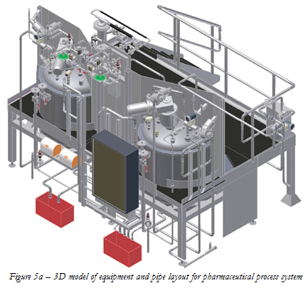
The layout of equipment and pipe routing is greatly
aided by the use of 3D modeling software (see Figure 5a and 5b) which allows
piping designers to visualize the complete installation and zoom in on
congested areas to check for clashes of valves and instrumentation. Extensive component libraries allow the
designer to quickly import standard components to compile the system model
which can then perform static and dynamic stress analyses on pipe and equipment
and indicate the best positions for anchors and supports. Individual isometrics can be exported with
bills of materials for purchasing to procure the necessary materials and the more
sophisticated packages can be linked with ERP systems to provide a complete
costing tool.

2.2 Valve Selection
For liquid piping systems, valves are the
controlling element. Valves are used to isolate equipment and piping systems,
regulate flow, prevent backflow, and regulate and relieve pressure. The most
suitable valve must be carefully selected for the piping system. The minimum design
or selection parameters for the valve most suitable for an application are the
following: size, material of construction, pressure and temperature ratings,
and end connections. In addition, if the valve is to be used for control
purposes, additional parameters must be defined. These parameters include: method of
operation, maximum and minimum flow capacity requirement, pressure drop during
normal flowing conditions, pressure drop at shutoff, and maximum and minimum
inlet pressure at the valve. These parameters are met by selecting body styles,
material of construction, seats, packing, end connections, operators and
supports.
2.3Ergonomics of Piping Design
While construction schedule and costs drive mechanical contractors to
install piping systems quickly it must be remembered that the final system will
be operated for many years in the future.
For this reason it is critical that proper consideration be given to the
ergonomic layout of the equipment and instrumentation so as to ensure that the
operator can comfortably operate the system.
Simple things such as gauges at an ergonomic height, orientated in an
upright position and with readable sized scales can make the monitoring and
recording of information so much easier.
Ease of access to equipment for periodic inspections and checking for
leaks will ensure that the plant is well cared for and well maintained. Space for removing equipment
`2.4 Case Study of a Centrifugal Pump Set Installation
 |
Isolation Valves
Pumps often need repairs. Sometimes
mechanical seal leakages occur. Pump bearings also need replacement. In order
to carry out such repairs pump needs to isolated. It should have no process fluid so that it can
be worked upon. Installing isolation
valves ensures that no liquid flows towards the pump due to gravity from either
upstream or downstream of pump.
Strainer
A strainer is a 'filter' that prevents
undesirable solid particles to flow upstream and clog the equipments. A
strainer contains a mesh that prevents the particles from flowing through it.
Two main types of strainers are: y-type strainers and basket strainers. Y-type
strainers (shown in figure 6) are used for relatively clean fluids while basket
type strainers are used where greater amounts of particles are present. When running a pump for the first time it is
vital that the strainer is checked on a regular basis as it will often clog up
with construction dirt and debris left over from the system fabrication.
Check valve
Check valves are used to prevent backflow in
the system, if a pump was to malfunction the fluid which has been pumped upstream
would try to flow back towards the pump. In order to stop this from happening a
check valve is used.
3.0 Piping Systems Commissioning

3.1 Process Commissioning
Process
commissioning occurs between the time construction is complete and plant
startup commences. During this period
process commissioning personnel are occupied with the task of ensuring the
facilities have been constructed and assembled according to the engineering
design and the equipment manufacturer’s directions. The objective is to ensure that the equipment
has been properly installed and is ready to receive process materials and operate
as originally conceived.
While
this list is not exhaustive the following points should be considered when
preparing for safe start-up and commissioning of ancillary piping equipment:
·
Commissioning plan and procedures must be
prepared that describe in detail how the various tests will be conducted and
evaluated.
·
A commissioning team assembled of experienced
managers, engineers, plant operators and fitters (these may be from the mechanical
contractor who installed the facility) acting as support staff.
·
The process commissioning procedures must also
describe safety precautions that must be taken before, during, and after the
commissioning process.
·
The detailed commissioning plan should
synchronize the turnover of process units from the mechanical contractor to the
commissioning team.
·
Before the commissioning team will accept any
packages the following should be signed off and available :
a.
DQ and basis of design for each of the systems
in the facility
b.
P&ID System walk-downs
c.
Flushing and
pressure test, test packs.
d.
Chemical cleaning and passivation
e.
IQ and OQ documentation
f.
Equipment suppliers documentation and Operation
and maintenance (O&M) manuals
·
Project planning software, should be used to
organize and control the commissioning process, so that resources can be
scheduled and deployed in the most effective way to ensure that all elements
are eventually commissioned and declared operable.
·
It is essential that there is accurate progress
reporting and feed back from the field, as more often than not the
commissioning of the next system is dependant on the first being a success.
Just
as with the actual construction of the process facility, process commissioning
is a complex activity covering all aspects of the newly constructed facilities.
·
Each element of the process unit is examined and
tested.
·
Process control valves must be stroked,
·
Controller tuning coefficients must be checked.
·
Sensors and analyzers must be calibrated
·
Relief valve settings must be checked,
·
Piping and equipment is often hydrostatically
tested or tested with inert gas again to find and eliminate any leaks which may
occur from final assembly or fitting of sensitive instruments which were
removed for the system pressure test.
·
Strainers, filters and tramp metal collectors
must be installed at critical locations in the piping system to prevent damage
to pumps and control valves.
Coordination
between trades is essential and tasks such as the following will need two or
more trades to verify:
·
Insulation must be inspected and steam tracing
tested.
·
Electrical connections must be checked and
electrical equipment tested where and when it can be done safely.
·
Rotating equipment must be checked for alignment
and manually rotated to ensure there are no interferences. Electrical motors
need to be run to ensure the connections are correctly installed and that the
motor rotates in the correct direction.
Should
problems develop during the startup phase, written plans and procedures should
be in place to empty each process unit in a safe and environmentally compliant
manner so that whatever problems occurred can be fixed. Any defects found during he commissioning
process must be corrected by the contractor before the process unit commissioning
can be declared as complete.
A
major part of process commissioning is in preparing the operating instructions for
the startup of the process. The procedures for a newly constructed plant often
differ from the procedures that would be placed in service after a successful
production campaign. In the case of a newly constructed plant, the procedure
may call for each upstream unit to be brought up to operating temperatures and
pressure and held for a period of time to validate the integrity of the unit
before process material is allowed to flow to the next downstream unit.
3.2 Piping systems Documentation and Validation
More
and more industries have placed an increasing emphasis on quality standards and
documentation in order to expedite their approval process for either their own
internal corporate quality requirements or for external bodies such as the IMB
(Irish Medicines Board) or the FDA (United States Food and Drug Administration). The approval process requires that the
facility in which a new product or drug is produced must be designed,
constructed and commissioned so that it meets the criteria for process
validation.
Validation
is the action of proving, in accordance with the principles of GMP (Good
Manufacturing Practice), that any procedure, process, equipment, material
activity or system consistently leads to the expected results. Documented
evidence provides a high degree of assurance that a specific system, equipment
or process will consistently produce a product meeting its pre-determined
specifications and quality attributes. To put it simply, validation is nothing
more than proving that a process actually works.
Failure
to achieve validation on the first attempt can be very costly to the facility
owner, so maintaining quality from the design phase throughout the construction
process is essential. To this end the
pipe fitter / welder can play a major part in ensuring the following documents
are maintained and collated in a controlled fashion:
·
Collecting and filing material certification for
goods received on site
·
Collecting and filing equipment documentation
and manuals for equipment received on site
·
Use the correct tacking and weld procedures and
ensure that all personnel welder qualifications are kept current.
·
Accurate maintenance of weld record sheets and
isometrics during the fabrication and installation phase.
·
Co-ordinate with inspection companies to ensure
weld inspection is maintained at or above the required % level or that all welds
are examined where 100% traceability is required.
·
Ensure
test packs are completed in the required format and signed off and witnessed by
the relevant personnel
·
Ensure any re-routings or changes in drawings
are recorded properly and that the information is relayed through the proper
channels to ensure accurate “As-built” drawings are handed over to the client.
Exercises
·
Identify 2 advantages and 2 disadvantages of a
plate and frame heat exchanger
·
Identify 2 reasons as to why a centrifugal pump
would be chosen before an air operated diaphragm pump
·
List 3 reasons why good equipment and piping
layout planning is vital for the operation of a facility after handover.
·
Dismantle and examine a pipe strainer and explain
how it protects equipment upstream.
·
Identify 3 ways how a pipe fitter can contribute to
the documentation process for system validation.